Parts:
P1,P2___________10K  Linear Potentiometers
                     (twin concentric-spindle dual gang for stereo)

R1_____________100K  1/4W Resistor
R2,R6___________18K  1/4W Resistors
R3_______________3K3 1/4W Resistor (18K for shelving curves: see Notes)
R4,R5____________1K8 1/4W Resistors (10K for shelving curves: see Notes)
R7_____________560R  1/4W Resistor

C1_______________1µF  63V Polyester Capacitor
C2_______________4n7  63V Polyester Capacitor (3n3 for shelving curves: see Notes)
C3_______________1µ5  63V Polyester Capacitor (100nF for shelving curves: see Notes)
C4,C7__________100nF  63V Polyester Capacitors
C5,C8___________22µF  25V Electrolytic Capacitors
C6,C9_________2200µF  25V Electrolytic Capacitors

IC1___________TL072   Dual BIFET Op-Amp
IC2___________78L15   15V 100mA Positive Regulator IC
IC3___________79L15   15V 100mA Negative Regulator IC

D1,D2________1N4002  200V 1A Diodes

SW1____________DPST  Toggle Switch

J1,J2__________RCA audio input sockets
J3_____________Mini DC Power Socket
Comments:
Needing a Tone Control, this module can be inserted in the chain between the Control Center and the Power Amplifier.The circuit is based on an original design of Reg Williamson, published on Electronics World + Wireless World, Circuit Ideas, January 1991.
This tone control circuit will take the form of either the traditional bass and treble adjustment or the shelving type, which is similar to a "tilt" control but with independent bass and treble.
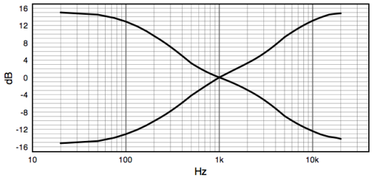
Asymptotic slopes for both are about 4dB/octave, but begin to flatten out at 100Hz and 10kHz, reaching a maximum of ±15dB at the ends of the audio band.
Component values in parenthesis are those for the shelving type of control. In this case, the shelf begins at about 250Hz and 4kHz, flattening to a ±6dB maximum an octave above or below; the central point is 1kHz.
Reactive elements for the low end include a generalized impedance converter, which simulates an inductor in series with a resistor (gyrator).
When set to the electrical centers of their respective controls, the reactive elements of the equalizers are virtually out of circuit. With these settings, the circuit behaves as a unity gain amplifier with 100% negative feedback. Even so, reactive elements can be switched out altogether with a DPST on/off switch.
As with the other modules of this series, each electronic board can be fitted into a standard enclosure: Hammond extruded aluminum cases are well suited to host the boards of this preamp. In particular, the cases sized 16 x 10.3 x 5.3 cm or 22 x 10.3 x 5.3 cm have a very good look when stacked. See below an example of the possible arrangement of the front and rear panels of this module.
Notes:
- To build the shelving type of control, use the values shown in parenthesis for R3, R4, R5, C2 and C3
- The circuit diagram shows the Left channel only and the power supply.
- Some parts are in common to both channels and must not be doubled. These parts are: P1 and P2 (if twin concentric-spindle dual gang potentiometers are used), IC2, IC3, C4, C5, C6, C7, C8, C9, D1, D2 and J3.
- This module requires an external 15 - 18V ac (50mA minimum) Power Supply Adaptor.
Technical data:
- Input sensitivity:
- 1V RMS for 1V RMS output
- Maximum output voltage:
- 9.5V RMS into 10K load
- Frequency response:
- flat from 20Hz to 23KHz
- Total harmonic distortion @ 1.5V RMS output:
- 100Hz = 0.004% 1KHz = 0.004% 10KHz = 0.002%
- Total harmonic distortion @ 6V RMS output:
- 100Hz = 0.003% 1KHz = 0.003% 10KHz = 0.03%
Traditional Bass and Treble Frequency Response
raditional Bass and Treble Frequency Response:


No comments:
Post a Comment