Related Posts Plugin for WordPress, Blogger...

Monday, December 30, 2013

Cable TV amplifier Circuits.

Description.
This is a very simple cable TV amplifier using two transistors. This amplifier circuit is most suitable for cable TV systems using 75 Ohm coaxial cables and works fine up to 150MHz. Transistor T1 performs the job of amplification. Up to 20dB gain can be expected from the circuit.T2 is wired as an emitter follower to increase current gain.Electronics Circuit Application


        Notes.
  • The circuit can be assembled on a Vero board.
  • Use 12V DC for powering the circuit.
  • Type no of the transistors are not very critical.
  • Any medium power NPN RF transistors can be used in place of T1 and T2.
  • This is just an elementary circuit. Do not compare it with high quality Cable TV amplifiers available in the market. Electronics Circuit Application

Sunday, December 29, 2013

Matrix LED display to 8051 microcontroller

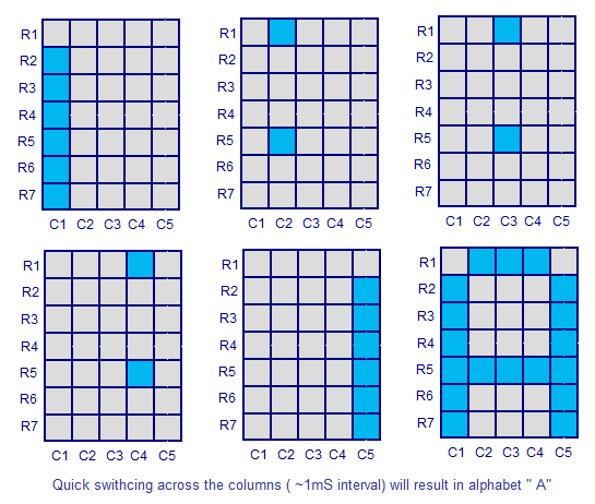
An LED dot matrix display consists of a matrix of  LED’s arranged in a rectangular configuration. The desired character or graphics can be displayed by switching ON /OFF  a desired configuration of LED’s. Common display configurations available are 7×5, 8×8, 7×15, etc. LED dot matrix can be used in simple display applications where the resolution is not a big concern.  The figure below shows the arrangement of LEDs in a typical 7×5 dot matrix display. Electronics Circuit Application

Any individual LED or a group of LEDs in the matrix can be activated by switching the required number of rows and columns. For example, in the above figure if  Row1 is made high and Column1 is made low, the top left LED (address R1C1) will glow. As a demonstration, lets see how we can display letter “A” using the display. The tables given below shows the logic levels at each pin  for displaying A. Electronics Circuit Application


 In the above diagram you can see that only one LED in a row will be ON at a time but any number of  LEDs in a column can be ON at a time.  That means the microcontroller’s port pin can directly drive a row but it requires  additional circuit for driving the column lines.  The circuit diagram for interfacing dot matrix display and 8051 microcontroller is shown below.Electronics Circuit Application


Circuit diagram
The purpose of ULN2003A here is to drive the column lines of the display. ULN2003A is a high voltage (50V), high current (500mA per channel) darlington transistor array. Each IC has 7 channels with individual output clamp diodes. ULN2003A  an active high device, which means a logic high must be applied to the input  to make the corresponding output high. The input pins are designated as 1B, 2B, 3B, 4B, 5B, 6B, 7B while corresponding output pins are designated as 1C, 2C, 3C, 4C, 5C, 6C, 7C.  The pin configuration and simplified internal logic of ULN2003A is shown in the figure below. Electronics Circuit Application
 
Program.
ORG 00H
MOV P3,#00000000B        // initializes port 3 as output port
MOV P1,#00000000B        // initializes port 1 as output port
MAIN: MOV P3,#01111110B
      MOV P1,#11111110B
      ACALL DELAY
      MOV P3,#00010001B
      MOV P1,#11111101B
      ACALL DELAY
      MOV P3,#00010001B
      MOV P1,#11111011B
      ACALL DELAY
      MOV P3,#00010001B
      MOV P1,#11110111B
      ACALL DELAY
      MOV P3,#01111110B
      MOV P1,#11101111B
      ACALL DELAY
      SJMP MAIN         // jumps back to the main loop
DELAY: MOV R6,#255D     // 1ms delay subroutine
HERE: DJNZ R6,HERE
      RET
END Electronics Circuit Application

Thursday, December 26, 2013

digitally selected output Adjustable regulator circuits

A very simple adjustable regulator circuit with digitally selected output is shown above. The circuit is a just a modification of the ordinary voltage regulator using LM317. Parallel to the resistor R4, four more resistor branches each with a transistor switch is added and these resistors can be included or excluded in to the circuit by making the corresponding switching transistor ON. In simple words the output voltage will be according to the logic level of the digital inputs A, B, C and D. Logic high at terminal A will make Q1 ON and so resistor R5 will be added parallel to R4 and so on. Addition of each resistance in parallel to the R4 will reduce the effective resistance of the path and so the output voltage of the resistance will decrease in steps. The width of each step depends on the value of the resistors you choose. Resistor R4 sets the maximum output voltage and it is according to the equation V out Max = 1.25V (1 + (R4/R3)) + (Iadj x R4).Electronics Circuit Application

Wednesday, December 25, 2013

LM317using Typical positive voltage regulator circuit

Few useful circuits using the voltage regulator IC LM317 is shown here. LM317 is a three terminal voltage regulator IC from National Semiconductors. The IC is capable of delivering up to 1A of output current. Input voltage can be up to 40V and output voltage can be adjusted from 1.2V to 37V.

 Electronics Circuit Application

Thursday, December 12, 2013

2 transistor siren circuit

The siren circuit is what importance in various alarm. For example : the emergency alert, burglar alarm circuits, Fire alarm circuits, Timer , sensor controls, etc. If we have not these circuit, We will not able to recognize the functionality of the circuit,we set out.
Operation of the circuit is Q1 and Q2 will work with R3, R4 and C2 is a frequency generator circuit with output connected to LED1 and speakers SP1. When I press the switch S1 to the C1 will begin to charge allows the voltage to pin B of Q1 increase other. The Q1 is working and Q2 is working with at the C1 charge full cycle will stop oscillator speaker is not.
The LED1 light and hold the release the pressure switch S1, resulting in C1 will start discharger through R3, Q1 to ground. The oscillator circuit sound Sirens in the lower out. If we press the switch S1 and then quickly leave many. The sound will be as continuous as C1 to charge and discharge alternately continuously.Electronics Circuit Application
circuits diagram
 

Wednesday, December 11, 2013

5V 1A Switching regulator by IC LM2575-5 Circuits

The switching regulator which used LM2575-5.0 in this page. You can make the stable voltage by using the 3 terminal regulator like LM317. However, because the output electric current and the inputted electric current are the same approximately, the difference between the input electric power (The input voltage x The input electric current) and the output power (The output voltage x The output current) is consumed as the heat with the regulator. Because it is, the efficiency isn’t good.


Data sheet for LM2575

Monday, December 9, 2013

LM3909 using 1.5V Battery or 3V Monitor circuits

We come to add LED Flasher for Monitor the electric current of battery 1.5V and 3V. By use the integrated circuit LED Flasher or Oscillator. By the rate something flasher equal to 2V. This circuit eats electric a little current poor age the work of battery long can’t be like be usable. If friends use battery 3V as a result liberate pin 1 float keep. I hope that a friend may apply with Battery 1.5V or 3V Monitor Circuit

LM334 using Voltage Reference Circuits.

This Voltage Reference Circuit. It used LM334 (ADJUSTABLE CURRENT SOURCES IC)
By fix the trend is stable. It make the pressure that pay to come out have tall stability. By can fine decorate VR1 10K Adjust Voltage Output. And You can use Voltage Input power supply at +2.5V to +20V. cause be high class voltage Output be valuable 0.8-5.0V depend on fining decorates VR1 there.
LM334  cicuits

Wednesday, December 4, 2013

How to huawei hsdpa usb modem service ?

Powered by
Electronics Circuit Application
www.electronicsyard.blogspot.com

2N4851 Using 12V Battery charger Circuit

This is an automatic 12V battery charger circuit, they uses the power SCR and UJT are main parts.
And they will not work except the battery 12V to be charged with right polarity, so prevent errors as well. The battery voltage controls the charger and when the battery is fully charged, the charger will not supply current to the battery anymore.
2N4851


 The battery charging current through the SCR MCR3818, when it is triggered into the conducting state by the UJT 2N4851 relaxation oscillator. And the oscillator is only activated when the battery voltage is low. Vb2b1 of the UJT derive the battery voltage that to be charged, and since Vp = Vd = Vb2b1 ; the higher Vb2b1, the higher Vp. When Vp exceeds the breakdown voltage of the zener diode ZD1, the UJT will stop to work and the SCR1 will not conduct.
T1 =Primary – 30 turn #22 , Secondary – 45 turns #22
R1 = Series resistance to limit current through SCR so use MCR3818 at 20 amps.
The setting VR1, we can charge the battery as needed. Electronics Circuit Application

Tuesday, December 3, 2013

M7555 - Battery Status Monitor circuit

The low power LED flasher by ICM7555
Normally, when you need to use LED display status of the battery 6V-12V. Just add a resistor in series only. It is easy and saving.
But not cool and consumes more power.
- The impression of a bright that continuously. I think that did not noticeable it.
- When the LED light as well So consumes too much energy. Although the LED need voltage is 1.8V only, but it uses too current is 15mA-20mA.
A wise choice.
- The LED flashes very prominent.
- Find out how to use current less than 1mA. When several ten years ago. I’ve used a LM3909 of LED Flasher/Oscillator IC.It is built for a particular flashing light or low current led flasher so easy to make and includes a very small amount. But unfortunately. Now IC manufacturers stopped producing it.
But we also have the option of interest, may be better than. If you are familiar with the IC 555 is a relative of the family is ICM7555 (or 7555IPA) with the same features. However very low power consumption. Because the internal structure of CMOS, So works great.
You take a look that the circuit is easy like I said or not. As shown below. You see not wrong, it using only three pieces, it can make the LED to flashes. By pull current from the power supply is only 0.15mA. It is designed as a typical Stable multivibrators circuit. (If you do not understand see this web. We have several circuits)
Special! In normal circuit, the capacitor will discharge directly to ground. However, for this circuit, the capacitor is discharged through LED1, so that LED1 flashes intermittently.
Just this you have a simple battery monitor circuit by IPM7555 Some people would say that’s not worth it. This circuit is more expensive than the old method. However it can extend battery life by several times, or Adapted for low current power supply such as solar or other alternative energy sources. They result is the same. Electronics Circuit Application

Monday, December 2, 2013

Car brake lights by BC327 Circuits

his is the circuit add beauty to the brake lights of the car. With a display of 14 LEDs, visible clearly, for safety and beautiful. The installation format can fix by oneself as you like it.
This circuit use the astable multivibrator for generate a oscillate frequency so all LED flashing.

The working of the circuits
When enter the light brake voltage, makes have power supply 12V come in cause LED6-LED9 glow or On. Besides the trend will flow to change R2 go to bias pin base of Q1-BC327 PNP transistor and Q2-BC327, causes LED1-LED5 and LED11-LED14 the bright up. Which there are R1 and R3 help to limit a current that flow through LEDs enough liberate brake power supply 12V disappear make LED every switch off.


 parst list
Q1,Q2_______________BC327____50V 1A PNP transistorrs
LED1-LED14__________LED display as you want.
R1,R4_______________22 ohms 0.5 watts 5% resistors
R2__________________390 ohms_0.5 watts 5% resistors
R3__________________500 ohms__0.5 watts 5% resistors Electronics Circuit Application

Amplifier speakers delay circuits

This circuit is small-sized circuit at can build easy, and usable get easy between a loudspeaker with amplifier. By have relay be switch edit during opening-time switch that stereo will hear the sound “Tlub” come out from loudspeaker. Which this sound is sound the electricity will pull sharply to flow enter still a loudspeaker and may will make a loudspeaker can are damaged therefore then necessary to must have time drag while open switch for a moment. For speak this part disappear before then build enter still a loudspeaker.

When receive power supply come in, The C1 will charge thereafter C2 begin charge change R1. When C2 charge full until go to bias give Q1 work go to current driver give relay. Which use relay model double contract, make contract switch touch. From that time build a loudspeaker suits power amplifier the period will delay to depend on the value C2. If want to give can delay long ago enhance the value C2. But if give can delay short down devalue C2.
Now, You do want to make this project. Electronics Circuit Application